Envelope Engineering/Manifesto/Computational engineering

Computationalengineering for facades,code, algorithm, AI.

For our atelier, computational design facade work is not a methodological option. It is the default stance. Where a traditional facade engineering office produces calculations and 2D drawings, we produce a signature: each of the four worlds of the envelope project (architecture, engineering, fabrication, installation) is augmented simultaneously by three digital levers (digital, algorithm, AI), to transform both the upstream process and the delivered outcome.

This is not an additional service bolted onto a 2D practice. It is the backbone of the practice itself. Our computational engineering facade approach is native, not adopted, because the industrial gesture and the algorithmic gesture were learned together rather than one after the other.

04worlds
architecture, engineering, fabrication, installation
03levers
digital, algorithm, AI
12cells
process improved and outcome guaranteed
17years
computational practice anchored in industry
01· Plate, computational manifesto

Our computational engineering is native.

A computational by nature practice, not a layer added to a 2D facade engineering office: native 3D modelling, algorithmic spatial simulation, parametric generation of geometries, direct flow from design to digital machining. What is drawn becomes fabricable because the data is never lost in transit.

§ 01A stance, not an option

Many engineering offices today claim a computational capability. Very few practise it at the heart of the process rather than as marketing veneer. Our atelier built it in from the start: parametric facade design, 3D spatial simulation, digital twins, are not tools called upon occasionally when a signature project demands them. They are the default working conditions.

The reason is twofold. On one side, the complexity of contemporary projects (free-form geometries, double curvatures, asymmetrical skins, discretised NURBS surfaces) cannot be resolved in 2D, or only at the cost of a loss of architectural intent and an unsustainable industrialisation cost. On the other, the pressure on schedule, budget and carbon requires that arbitrations be taken in design, on a simulated model, rather than on site where they cost ten times more.

§ 02Four worlds, three levers, twelve cells

The envelope project unfolds across four worlds that must dialogue from the sketch onwards: architecture (typologies, materiality, free-form geometries), engineering (active glazing, structural glass, demountable assemblies, hybrid systems), fabrication (file-to-factory flows, low-carbon materials, prefabricated components), installation (industrialised installation methods, optimised site logistics).

Each of these worlds is today augmented by three digital levers we mobilise coherently: digital (native 3D modelling, structured data exchange, digital twins), algorithm (parametric, computational optimisation, geometric generation), AI (design assistance, pattern detection, risk scoring, automatic quality control). The signature of the atelier rests on the rigour with which these twelve cells are held simultaneously, not on the isolated use of one tool or another. The result is a coherent computational design facade doctrine across the project.

§ 03Process improved, outcome guaranteed

For each of the twelve cells, two questions structure our reading. How does this lever improve the process? (cycles shortened, rekeyings avoided, arbitrations anticipated, traceability extended). How does it guarantee a better outcome? (architectural intent preserved, thermal performance held, defects detected in factory rather than on site, claims avoided, carbon reduced). Code, algorithm and AI are only of value if they hold both promises, one and the other, without sacrificing one in the name of the other.
02· Plate, canonical matrix

The signature grid, twelve cells held.

Diagrammatic reading of the four worlds of the envelope project, each augmented by the three digital levers. Each cell condenses what the augmentation transforms in the process and guarantees in the outcome. The argued cell-by-cell development is found in Plate 03.

Fig. 02, four worlds × three levers matrix, computational engineering signatureWorlds × levers · transformation of process and outcome
ScaleDesign → Handover
World 01Architecture
  • Digital, native 3D modellingProcess: design on a parametric environment shared across disciplines. Outcome: intent preserved across phases without loss of geometric fidelity.
  • Algorithm, parametric generationProcess: computational exploration of variants in real time. Outcome: free-form geometries rationalised into fabricable families without dilution of intent.
  • AI, design assistanceProcess: scanning of project banks and architectural patterns at scale. Outcome: the architect arbitrates faster with a documented reading of precedents.
World 02Engineering
  • Digital, connected simulationProcess: structural, thermal and acoustic calculations on the same native 3D model. Outcome: coherent arbitrations taken in design, not on site.
  • Algorithm, multi-objective optimisationProcess: structure, thermal and economics optimised in parallel rather than in sequence. Outcome: performances held without accidental overcost.
  • AI, risk scoringProcess: detection of thermal bridges, anticipation of claims, flagging of sensitive configurations from the normative base. Outcome: more robust execution dossiers at handover.
World 03Fabrication
  • Digital, file-to-factoryProcess: direct export to IGES, STEP, CAM formats, no intermediate 2D drawing. Outcome: full traceability of each part to its source parametric model.
  • Algorithm, material optimisationProcess: CNC nesting, machining sequences and component rationalisation automated. Outcome: material cost mastered and production defects reduced.
  • AI, quality controlProcess: in-line detection of dimensional and surface deviations. Outcome: defects stopped in factory rather than reworked on site or under decennial warranty.
World 04Installation
  • Digital, BIM4DProcess: installation sequences modelled before site, interfaces with other packages framed. Outcome: conflicts anticipated in office rather than arbitrated under schedule pressure.
  • Algorithm, installation logisticsProcess: crane and cradle sequences, bay ordering, optimised on the real site geometry. Outcome: heavy-equipment mobilisation time reduced, installation safety improved.
  • AI, drift anticipationProcess: tracking of real vs planned tolerances on site. Outcome: drifts detected before they crystallise into non-conformities.
Effective production, Envelope Engineering computational missions.Fig. 02, twelve cells · 1/1
§ Principle

No cell substitutes itself for the human substance of the craft; each cell frees engineers' time for the arbitrations only experienced humans can hold.

03· Plate, four worlds developed

Four worlds augmented in depth.

The grid of Plate 02 is here deployed pane by pane. Each world, its technical context, its three digital, algorithm and AI levers detailed, and the dual promise of process improved + outcome guaranteed. Click a world to read its full argument.

01
Architecture
augmented

The intent carried by data, not eroded by it.

Three levers hold the architectural argument against industrial constraints.

Digital, shared native 3D modelling. The project lives in a parametric environment shared between architect, engineer and fabricator. Exchanges are structured (open formats, digital twins), not degraded into PDF round-trips. The process shortens upstream validation loops. The outcome preserves intent across phases without loss of geometric fidelity between the sketch and the delivered part.

Algorithm, parametric generation of free-form geometries. On complex surfaces (double curvatures, asymmetrical skins, NURBS surfaces), we computationally explore variants: panel grid density, panel orientation, node articulation. The process executes in minutes what would take weeks of 2D redrafting. The outcome is a family of industrially fabricable panels that holds the geometric intent without forcing one-off bespoke fabrication.

AI, design assistance and reading of precedents. On indexed project banks and normative bases, AI helps to scan architectural patterns and comparable configurations rapidly. The process frees up arbitration time. The outcome is a documented reading of precedents that informs the decision without replacing it; the architect rules with a broader overview. This is the field where AI facade engineering begins to compound the architect's judgement rather than dilute it.

See our DNA, the dual industrial and computational culture →

Lever 01
Shared native 3D modelling
Lever 02
Parametric generation of free-form geometries
Lever 03
Design assistance and reading of precedents
RhinoGrasshopperParametric familiesDocumented patterns
§ Structural equation
The twelve cells only function simultaneously, on the same parametric model, from the early design phase onwards; isolated, they are mere tools; held together, they make the signature.

The most visible case of this signature, on the fabrication dimension, is our DFMA and file-to-factory practice. It is documented in a sister page that details the five DFMA facade axes, the six industrial capabilities we mobilise via our European Tier-1 network, and the concrete benefits by client profile. Read against the present manifesto, it shows how a single cell (Fab × Algorithm) deploys at the operational level of a mission. DFMA & file-to-factory, the applied case →

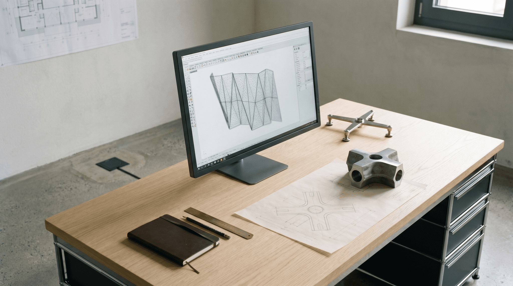
Swiss senior computational workstation, illegible parametric 3D screen, cast steel and spider fitting fragments on graphite tracing paper, atelier corner working sessionFIG. 04 · Workstation
01 / 04Computational atelier-laboratory, parametric 3D screen alongside physical fragments and graphite tracing paper.
© S&P
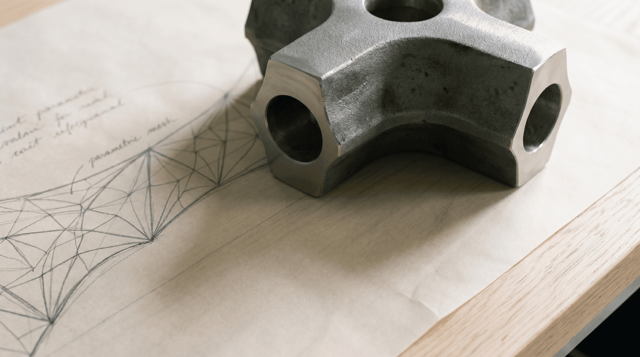
Macro cast steel structural sand-cast node placed on graphite tracing paper with cursive annotations, raking shadow at 20 degreesFIG. 04a · Cast steel
02 / 04Cast steel node, physical reference fragment on graphite tracing paper.
© S&P
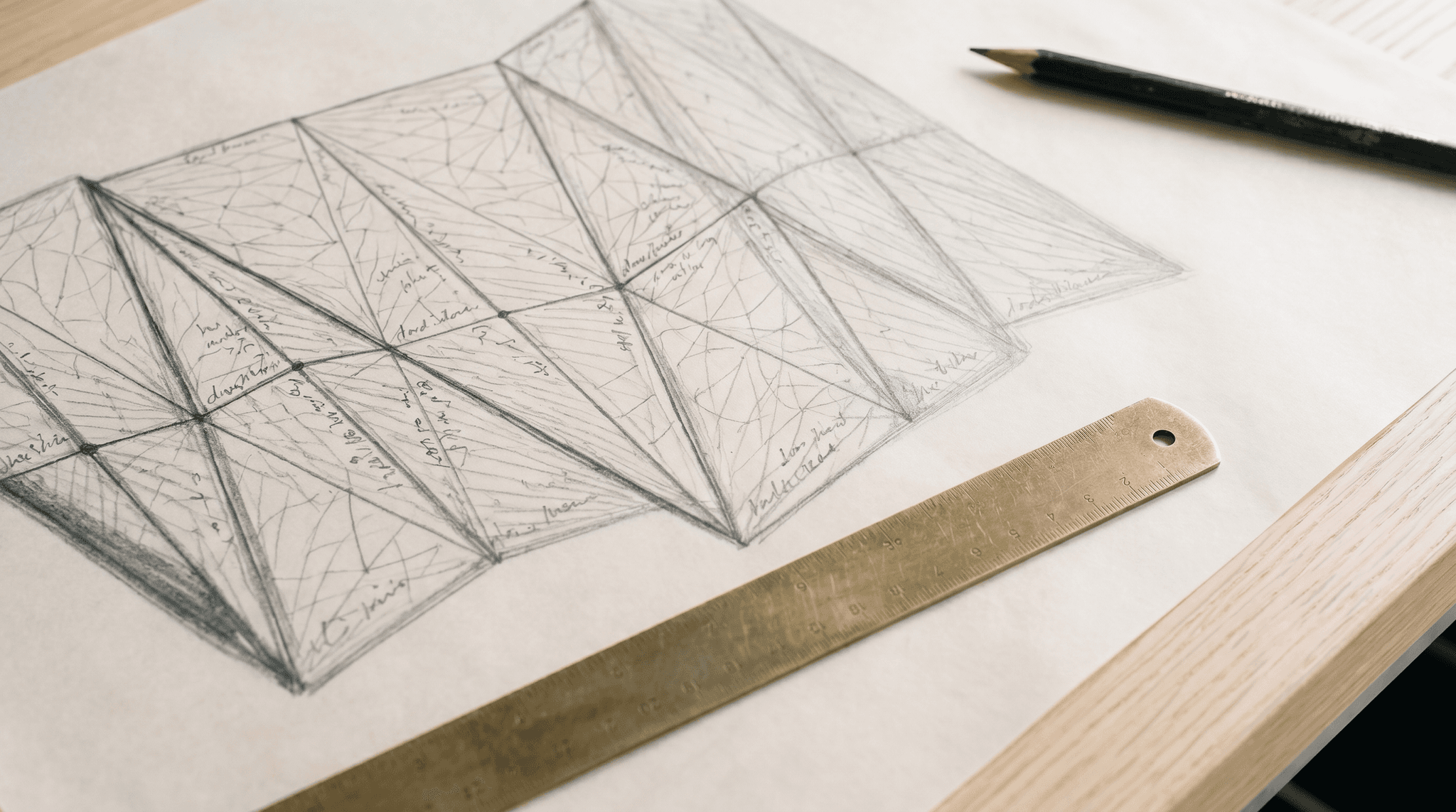
Macro graphite tracing paper, triangulated parametric mesh annotated in illegible cursive, patinated brass ruler on diagonalFIG. 04b · Parametric
03 / 04Parametric mesh, graphite linework and brass ruler.
© S&P
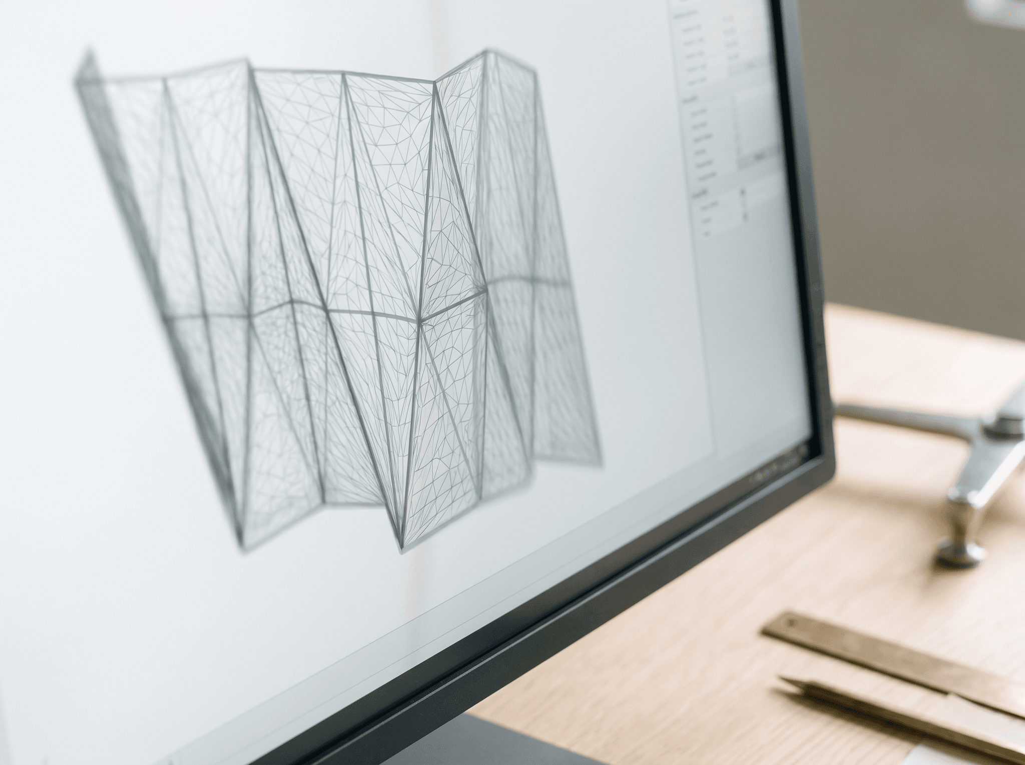
Macro workstation screen, illegible 3D parametric wireframe, free-form triangulated geometry, anthracite bezelFIG. 04c · Native 3D
04 / 04Native 3D parametric, free-form wireframe with no readable interface.
© S&P
05Plate 05 / 07, Project

Application on a reference project.

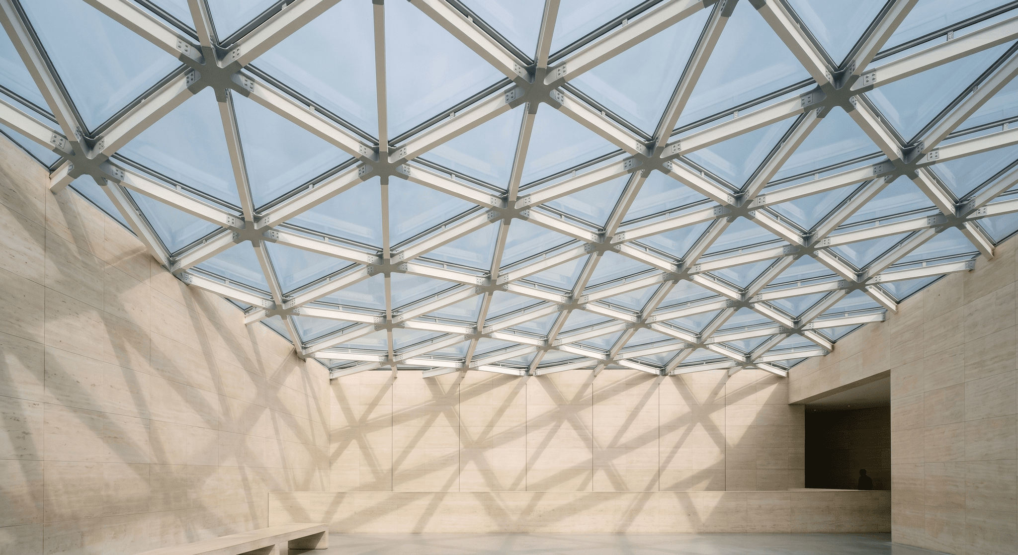
From the parametric atelier to the delivered atrium. Three zooms on a triangulated diagrid skylight with variable geometry, where each cast steel node and each glass pane is unique, algorithmically generated and fabricated through file-to-factory.

Signature institutional atrium, triangulated diagrid skylight with variable parametric geometry, raking shadows projected on travertineFIG. 05 · Atrium
01 / 04Signature atrium, triangulated diagrid skylight, variable parametric geometry.
© S&P
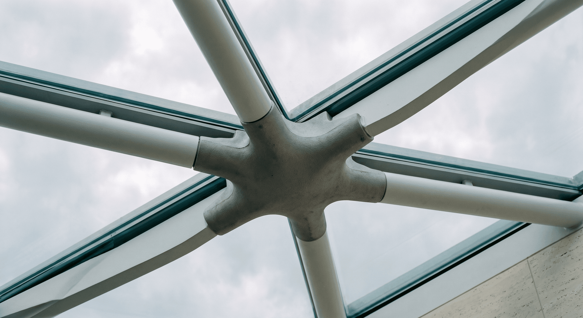
Detail of cast steel structural node, six chords converging at variable angles, sand-cast micro-texture, viewed from the atriumFIG. 05a · Node
02 / 04Cast steel node, six chords converging at variable angles.
© S&P
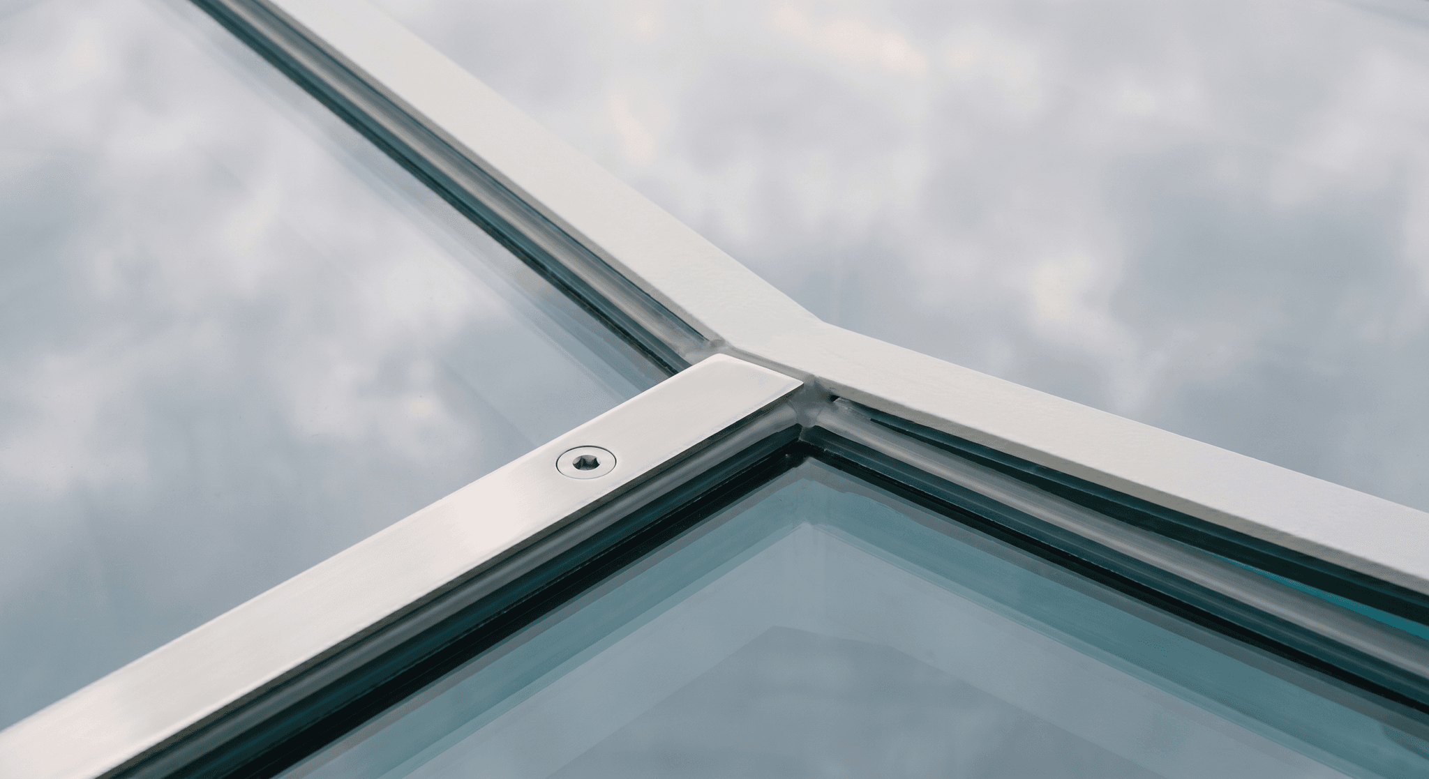
Detail of intersection of three triangular glass panels, polished stainless steel plate with machined bolt, structural silicone jointFIG. 05b · Panel
03 / 04Unique glass panels, stainless steel plate and structural joint.
© S&P
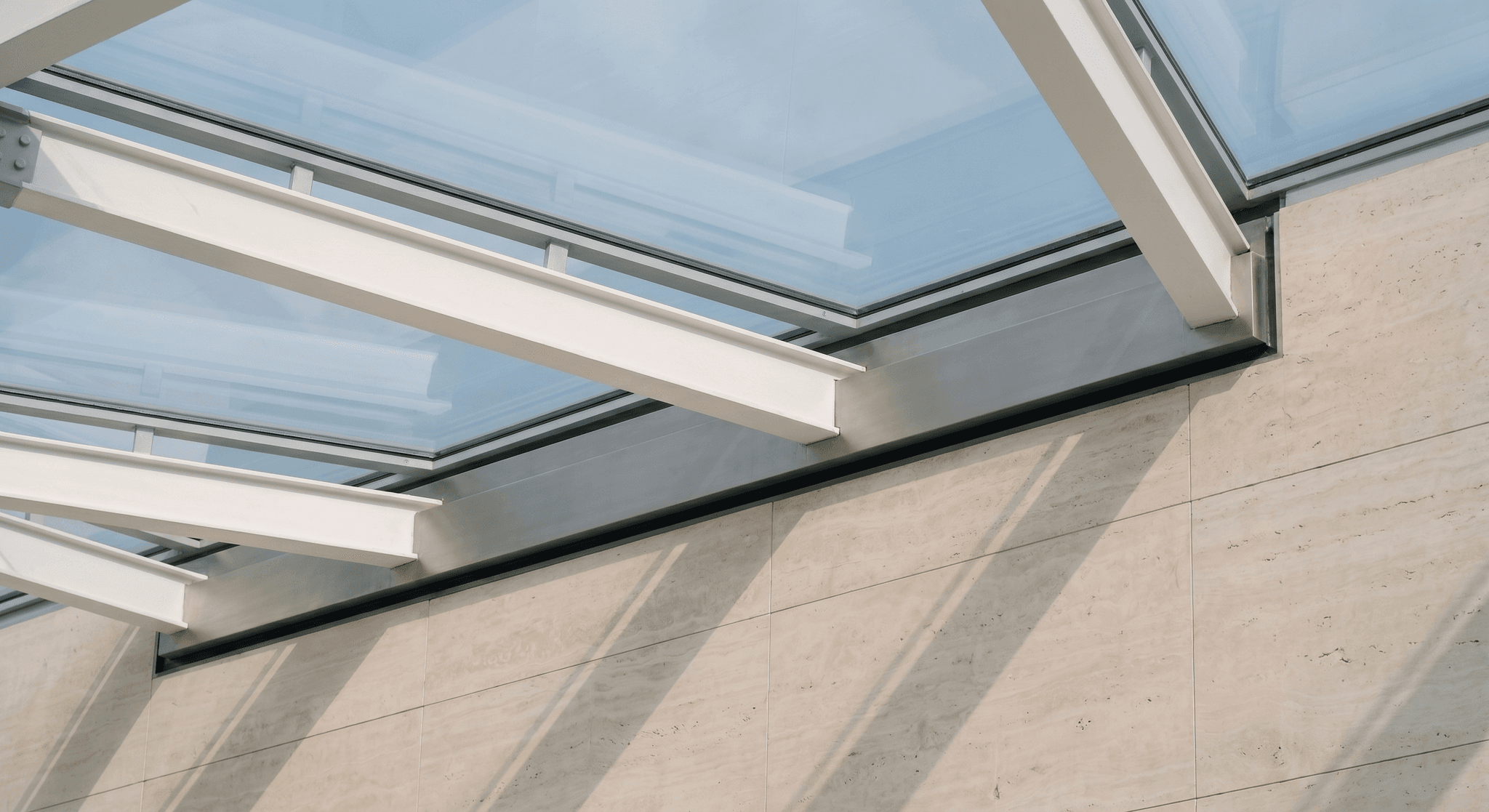
Detail of diagrid springline against travertine wall, stainless anchorage profile, raking shadows of the chords projected on the stoneFIG. 05c · Springline
04 / 04Diagrid springline, anchorage and shadow projection on travertine.
© S&P
06· Plate, stance and anchor

What makes the practice tenable.

Four elements make our computational engineering facade approach operationally tenable, where other engineering offices claim it without serving it. The first, posed upfront, is our dual industrial and computational anchor; three others complete it.

Distinctive element · 01 / 04

Dual industrial + computational anchor.

Seventeen years in the envelope industry, including several years in pre-construction with a Tier-1 international contractor in glass envelope works, give the fine-grained knowledge of what European supply chains actually produce: real aluminium extrusion tolerances, glass processing, mechanical assembly, frequent failure modes in production. Combined with a native computational practice (3D modelling, parametric, digital twins practised from the atelier's first day), this anchor lets us industrially translate any geometry without compromise on intent.

02 / 02Distinctive element

Technological neutrality

No software-vendor affiliation, no licence commission, no fixed ecosystem imposed.

When we recommend one computational environment over another (Rhino + Grasshopper on free-form surfaces, BIM standards on international design-team projects, open exchange formats on file-to-factory chains), it is because the ecosystem fits the project better. Not because the vendor pays us a kickback. The rule is documented contractually. See Technological neutrality.

No commissionPerformance criteriaOpen ecosystem
03 / 03Distinctive element

Internal AI resources

State-of-the-art language models mobilised in-house on recent AI missions.

On missions where the AI dimension is central (transformation of a facade contractor's engineering office, risk scoring on execution dossiers, computational reading of normative bases), our internal resources mobilise the most advanced language models available to the atelier. The driver is operational: the reasoning quality of these models has become, on certain arbitrations, an operational advantage. Not a demonstration. See Digital & AI transformation for the sister reading on the business side.

Advanced LLMsScoringNormative reading
04 / 04Distinctive element

Systems thinking

The twelve cells articulate; they do not add up.

Computational engineering is not an accumulation of tools. It is a coherence across the twelve cells: a file-to-factory export only holds if the upstream modelling is parametric, which only holds if the engineering multi-objective optimisation has not been done outside the model, which only holds if the architect has accepted the computational grammar from the sketch onwards. This coherence is what makes the method operational; it is built over time, not through a string of software purchases. facade algorithms are only as effective as the systemic discipline that holds them together.

CoherenceNo additionBuilt over time
07· Plate, continue reading

Continue reading.

Six entry points to explore how computational engineering embodies itself across each of the four worlds and how it articulates with the Business Engineering pillar.

A project to industrialise through code?

A free-form geometry to rationalise computationally, a file-to-factory workflow to structure, an AI-augmented transformation of a facade engineering office to scope. Describe the context. We come back with a reading of the digital, algorithm and AI levers adapted.

Computational brief
Shili & PartnersA Shili Build Ventures company